Take me home
CDi1/CDi3 Board Assembly Pictures
Keller Transmitter Assembly
RF Work
CDi1/3
Assembly Pics:
Solenoid Assembly Pictures
LF Work
Vinyl Works
Lake Erie Rescue
Overview
Different power sources, different communication speeds, different boards, identical assembly, identical operation from the software point of view, both deal with their attached single Kellers in digital mode. The CDi1 talks to the computer and to its Kellers at 9600 baud as the CDi3 does the same at 115200 baud, over 10 times faster. The CDi1 is a very old board, however, the potting process preserves its integrity quite well so it can still be used now or in the future. The "zombification" of the DS1386 RTC chip ensures the perpetuation of both devices well into the future as the *6Z assembly process described in this page adds decades to the service life of both devices. Other than having to change batteries every 8 to 10 years there is nothing else to do, in other words, maintenance is no longer required!
CDi3.FTe Battery Compartment and Lid (Assembly *6Z)
CDi1.FTe Battery Compartment and Lid (Assembly *6Z)
OBSOLETE!!! Click [+]
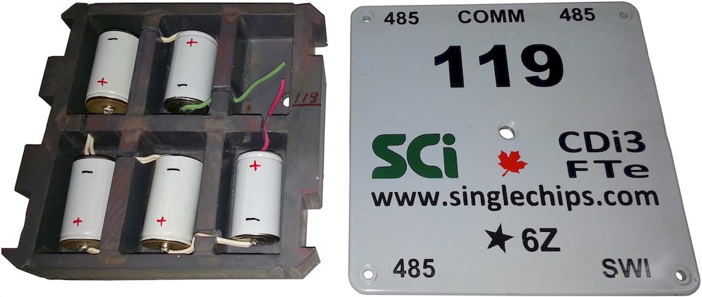
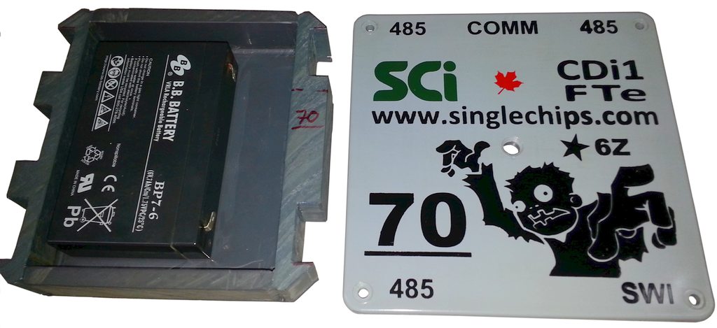
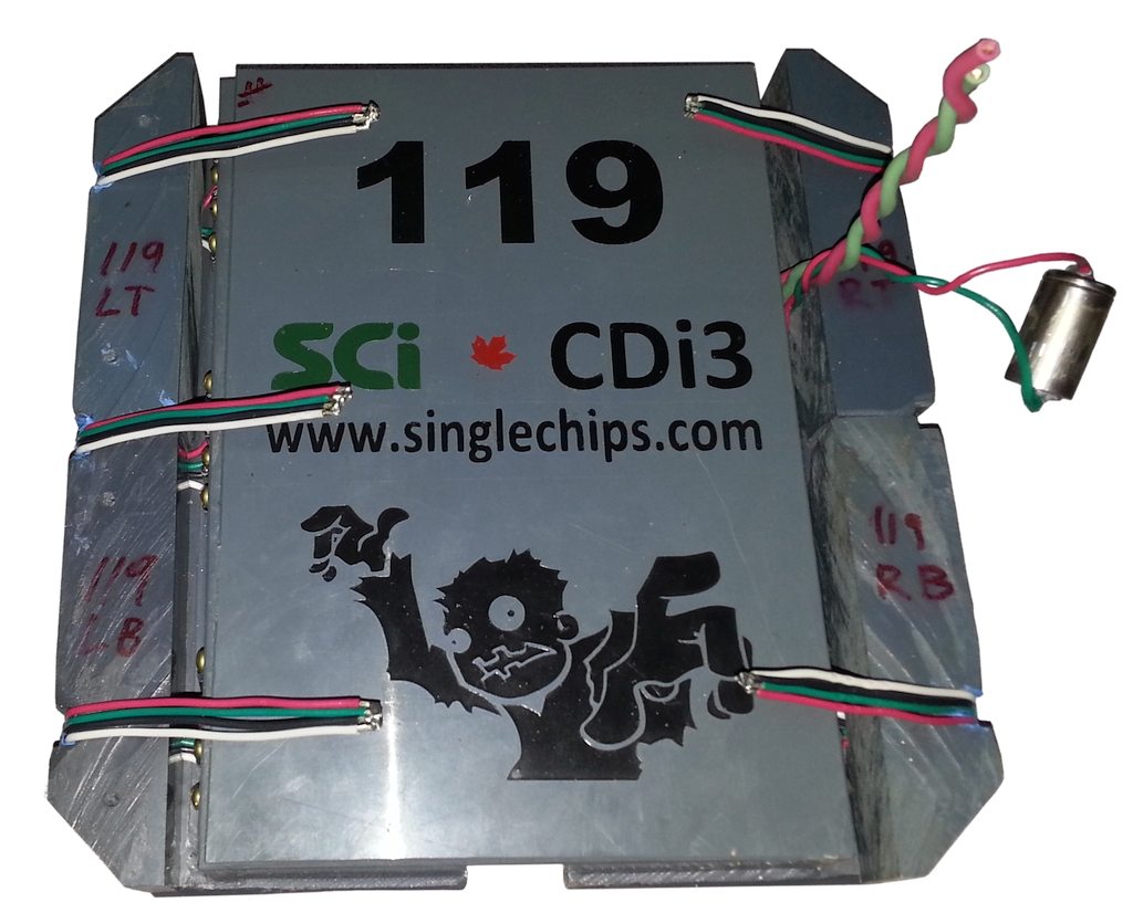
New CDi1/CDi3 Assembly Method *6Z Pictures, August-September-October 2018
  • 24th Anniversary Edition Assembly Method!
  • Operation "flip the plastic" places the battery compartment at the top of the assembly so the batteries can be changed without having to destroy the outer PVC box. The pictures in this section document this new assembly method, it is named *6Z, the "star" refers to the method itself, the "6Z" refers to the "zombified" DS1386 RTC chip. The old assembly method is documented in the next section below.

  • So two of the original digital P7s #118 and #119 which looked like this in June 2011, and one original analogue P5 #70 which looked like this in the spring of 2005 get a facelift! In addition to the facelift, the old analogue P5 also goes digital and so gets its real name back, and that is, of course, CDi1!
  • Obsolete! The CDi1 row of pictures below show how to add digital capability to an old P5 board and the *6Z related.
  • The CDi3 rows of pictures show the necessary changes to convert a 2010 P7MAIN board to a CDi3-class board and the *6Z assembly.
  • So the major steps are:
  1. Pot the board in its own compartment first
  2. Pot the board compartment at the bottom of the PVC box
  3. Connect the elbows
  4. Attach the battery compartment and finish the wiring
  5. Pot the battery compartment
  6. Test, test, test!
    CDi3:
    CDi1:
    Obsolete!!!
    Recovered CDi1 (P5) board after cleaning and after board lithium battery removal

    Bottom modifications
    Bottom modifications
    Top modifications, relay circuitry bottom left switches the two UART RX and TX lines between the main communications connector and the RS485 chip, middle right
    Top modifications, relay closeup
    Top modifications, RS485 detail. The "A" and "B" lines go out to the local RS485 Keller network
    CDi1 Battery compartment and lid
    Board compartment
    Board compartment with lid
    Board compartment with lid
    Board compartment with lid
    Board compartment with lid
    Board compartment with lid
    3M Potting Compound 2131 Size B, 2123 Size D
    3M Potting Compound 2131 Size B, 2123 Size D
    Recovered original boards from 2010-2011
    Original board closeup
    Board with zombified RTC
    Change 1: Board lithium battery eliminated
    Change 2: Board crystal changed from 6.144MHz to 7.372MHz
    Change 3:
    Change 4: Short the analogue channels with 10K resistor
    External wiring arrangement
    Internal wiring done
    What are you people smoking?
    Potted
    Potted
    Potted
    Bottom covered
    One elbow done
    One elbow done, two to go
    Two elbows done, one to go
    Three elbows done
    Try batteries for fit
    Check fit
    Check fit the other side
    Final testing before potting
    Potted
    Potted side detail
    Testing
    Testing
    Testing
    Testing
    Done!
    Elbows wired
    Elbows wired
    Elbows wired
    Battery compartment in place
    Battery compartment close up
    Battery compartment potted
    Potting close up
    Another view
    Potting close up
    Potting close up
    Done!
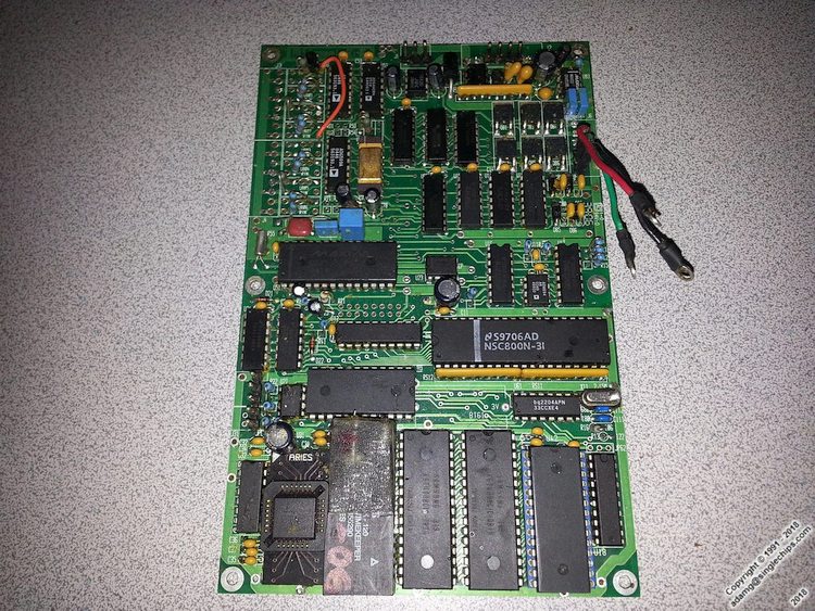
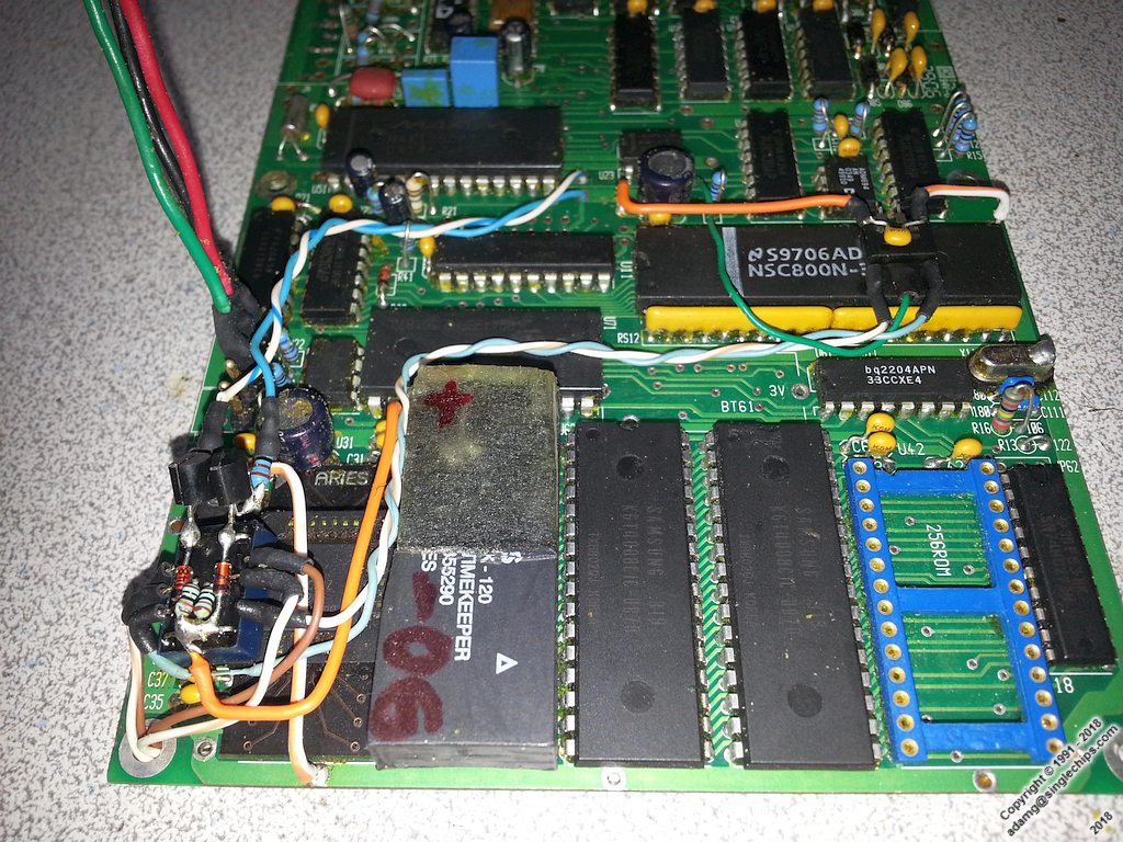
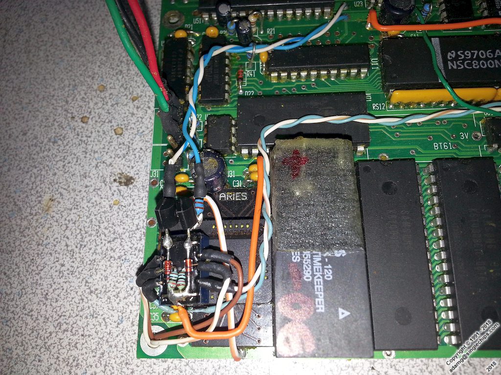
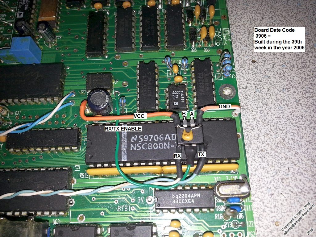
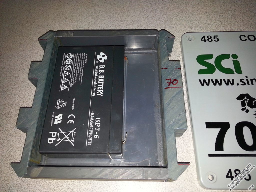
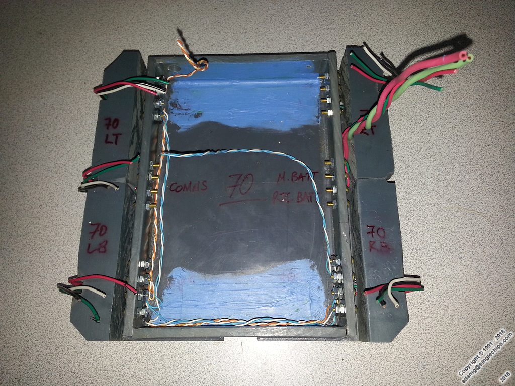
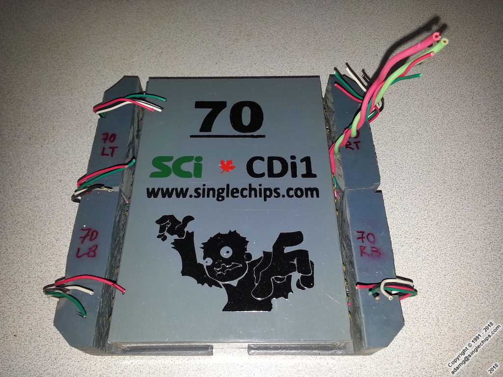
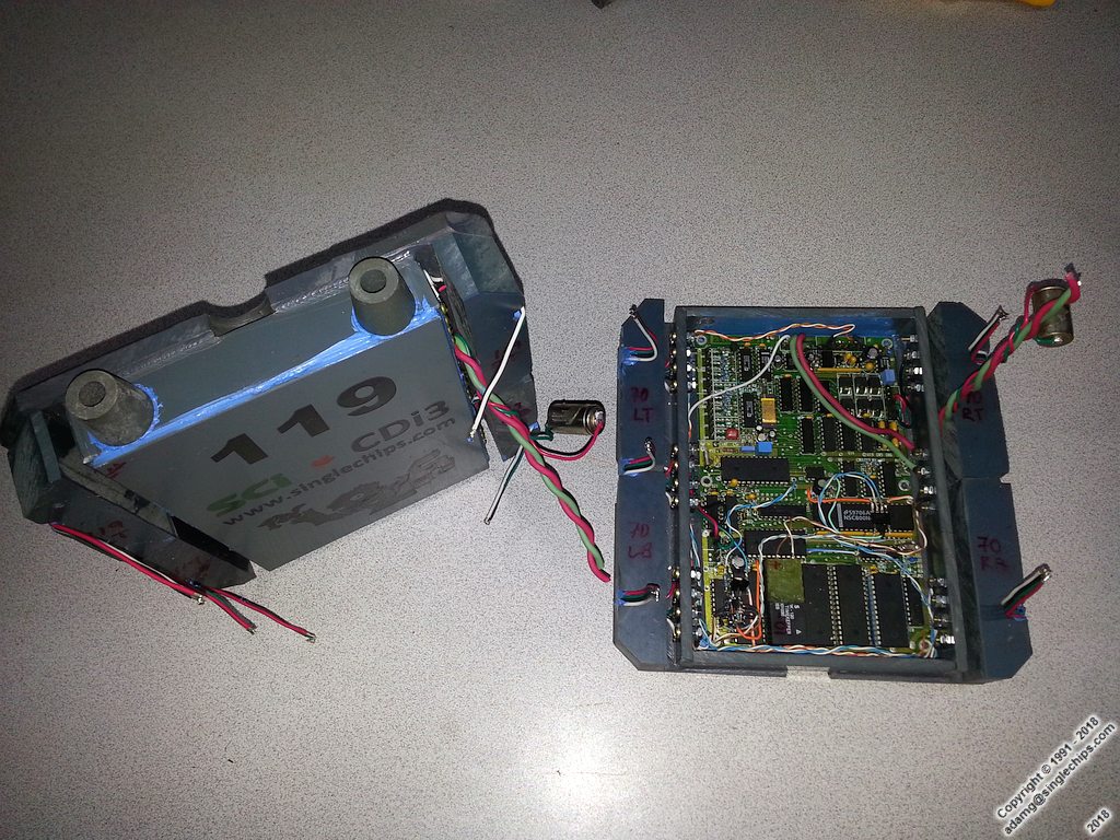
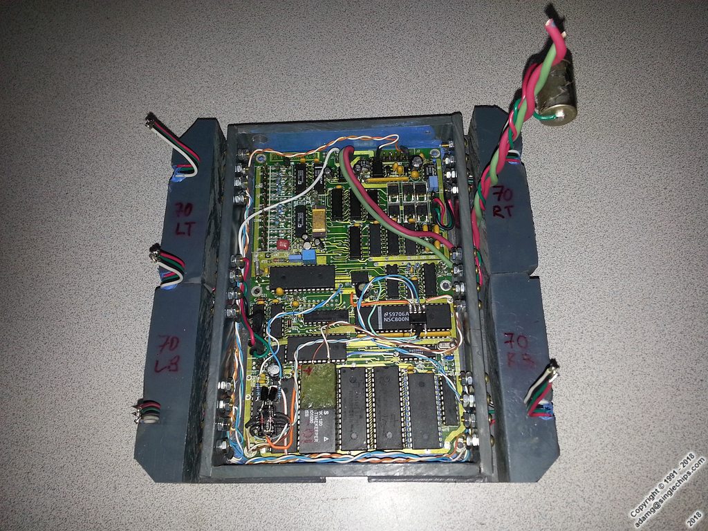
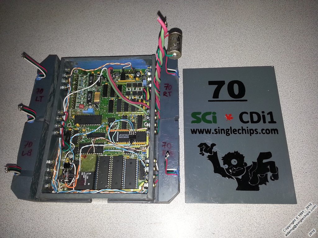
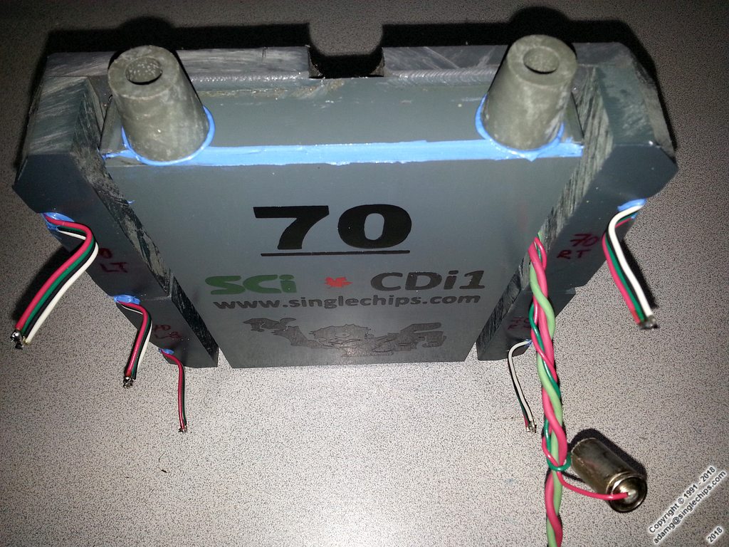
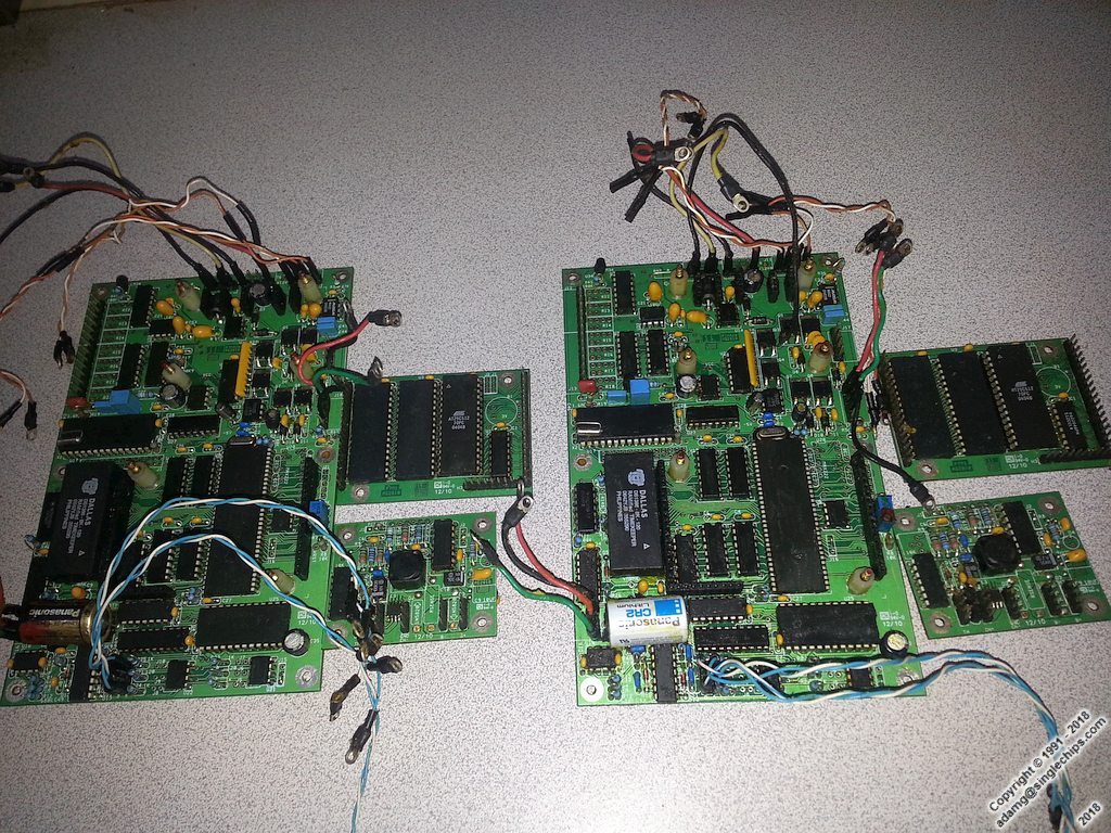
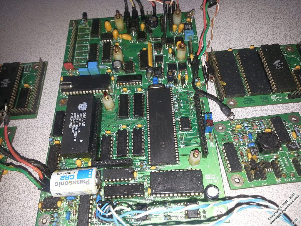
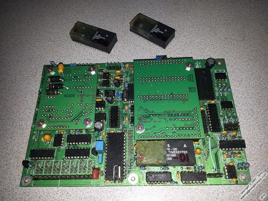
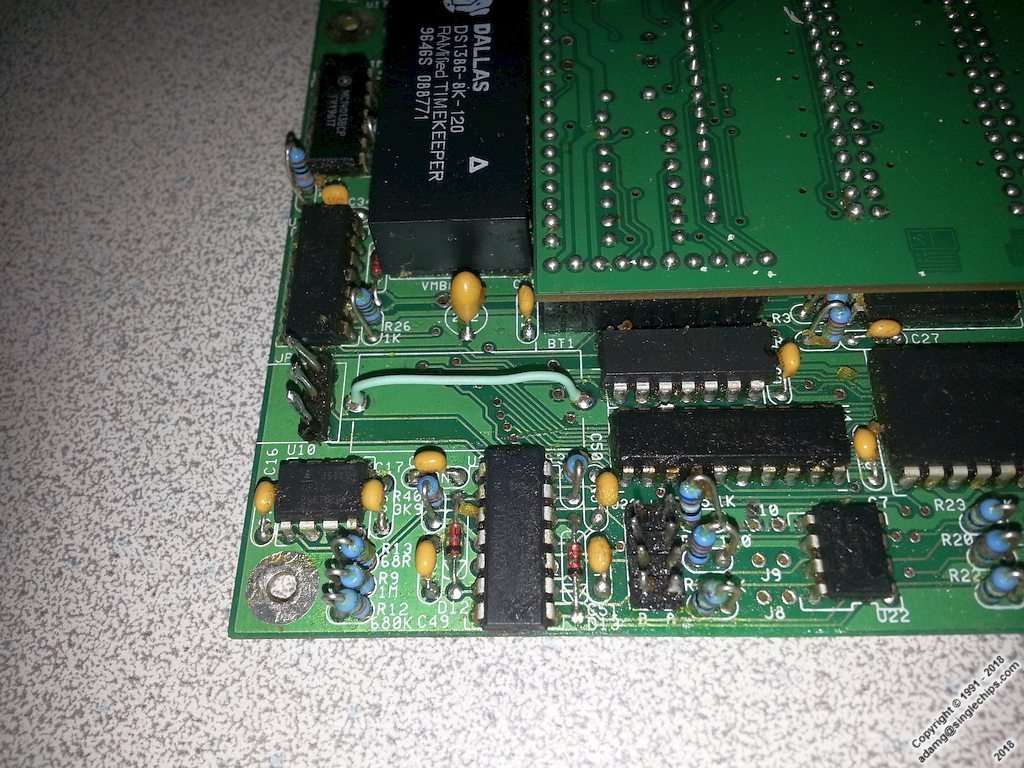
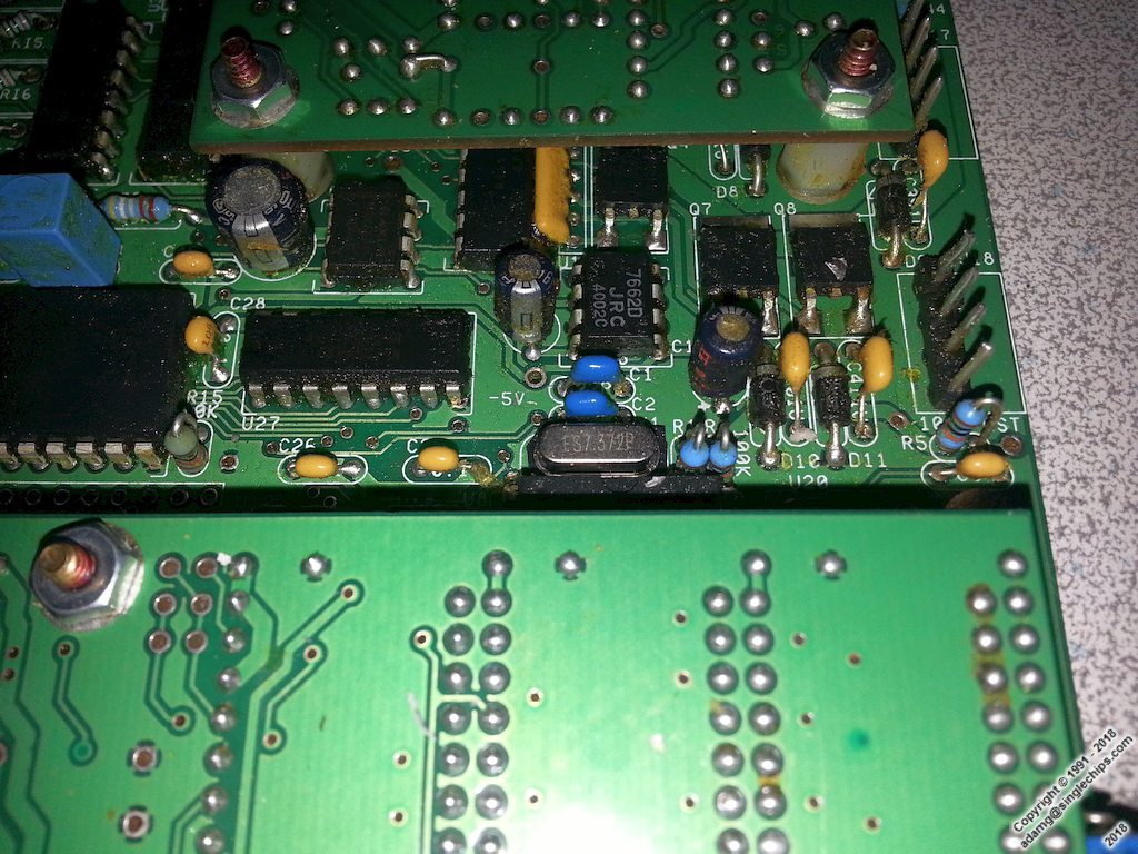
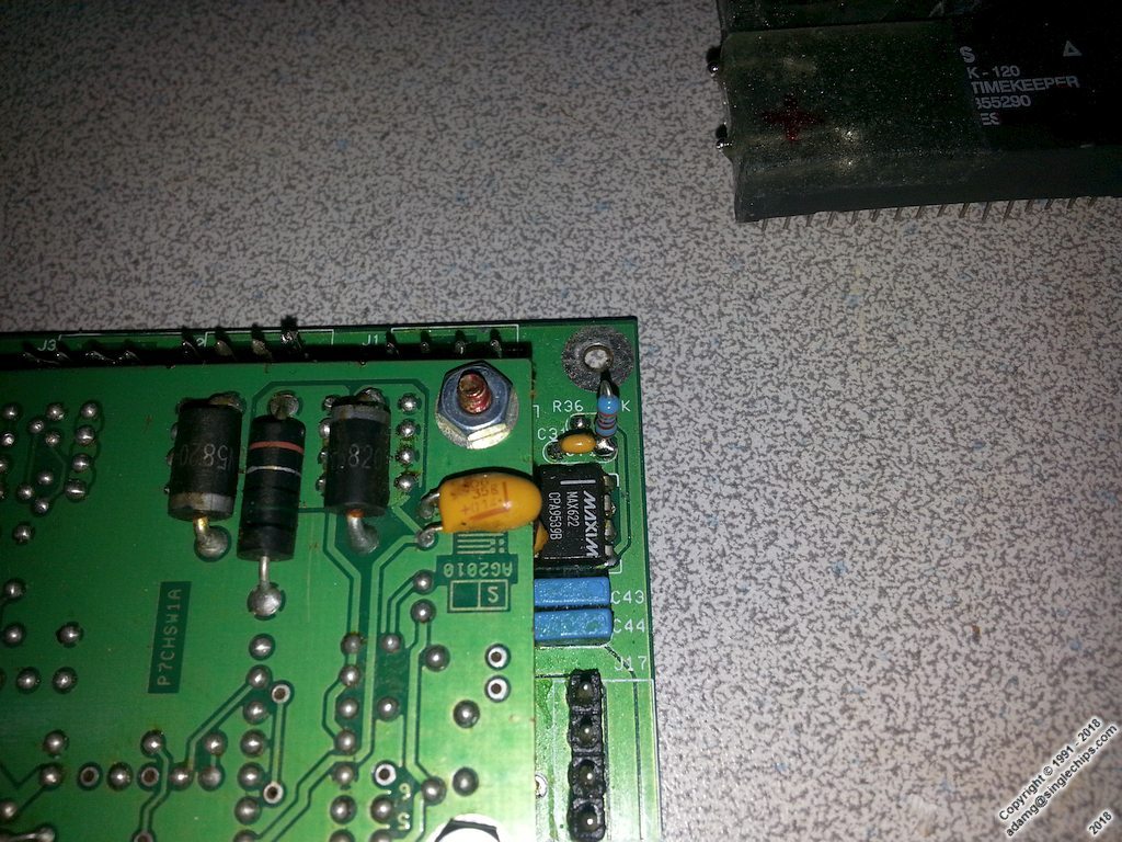
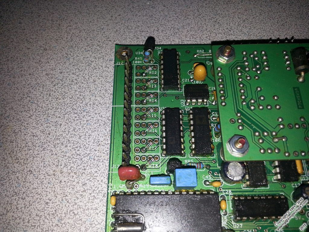
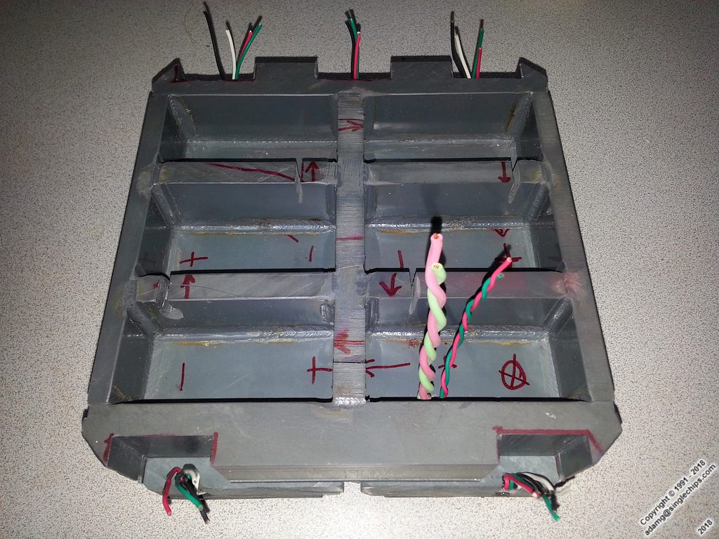
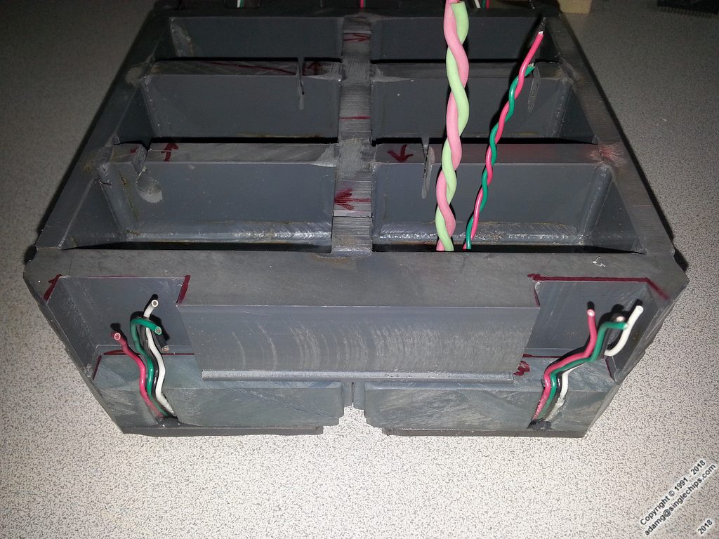
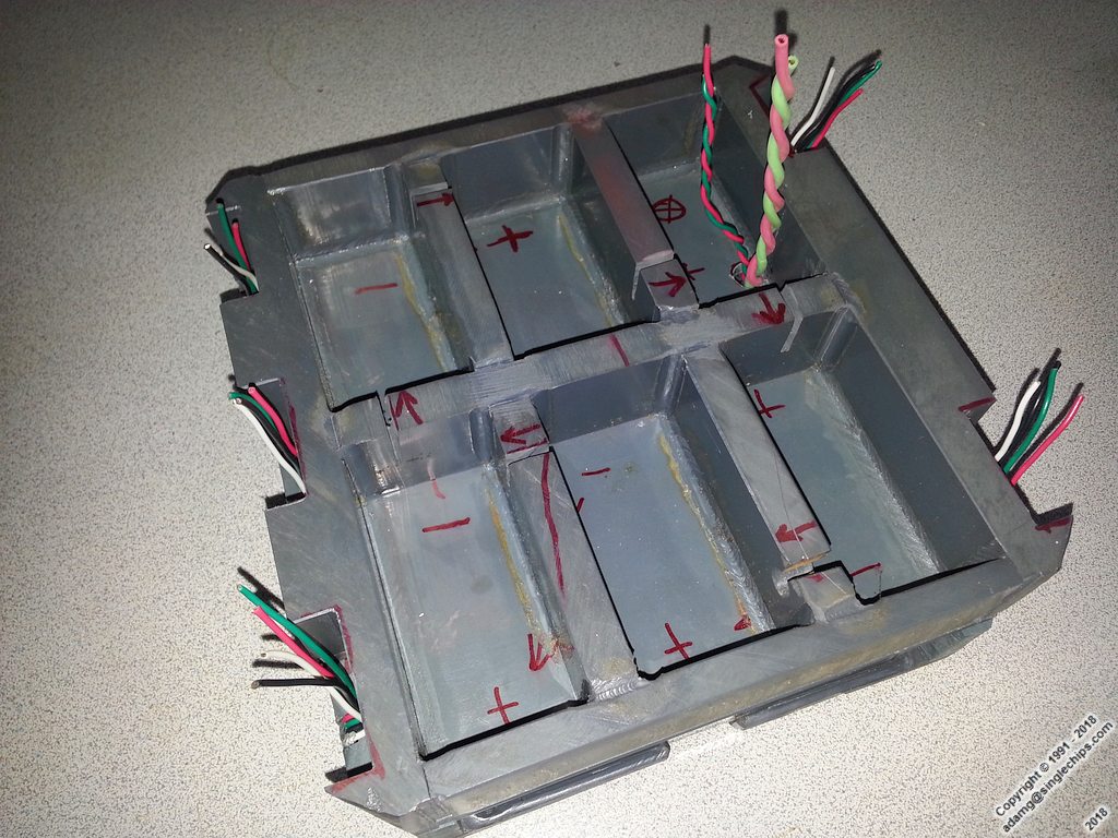
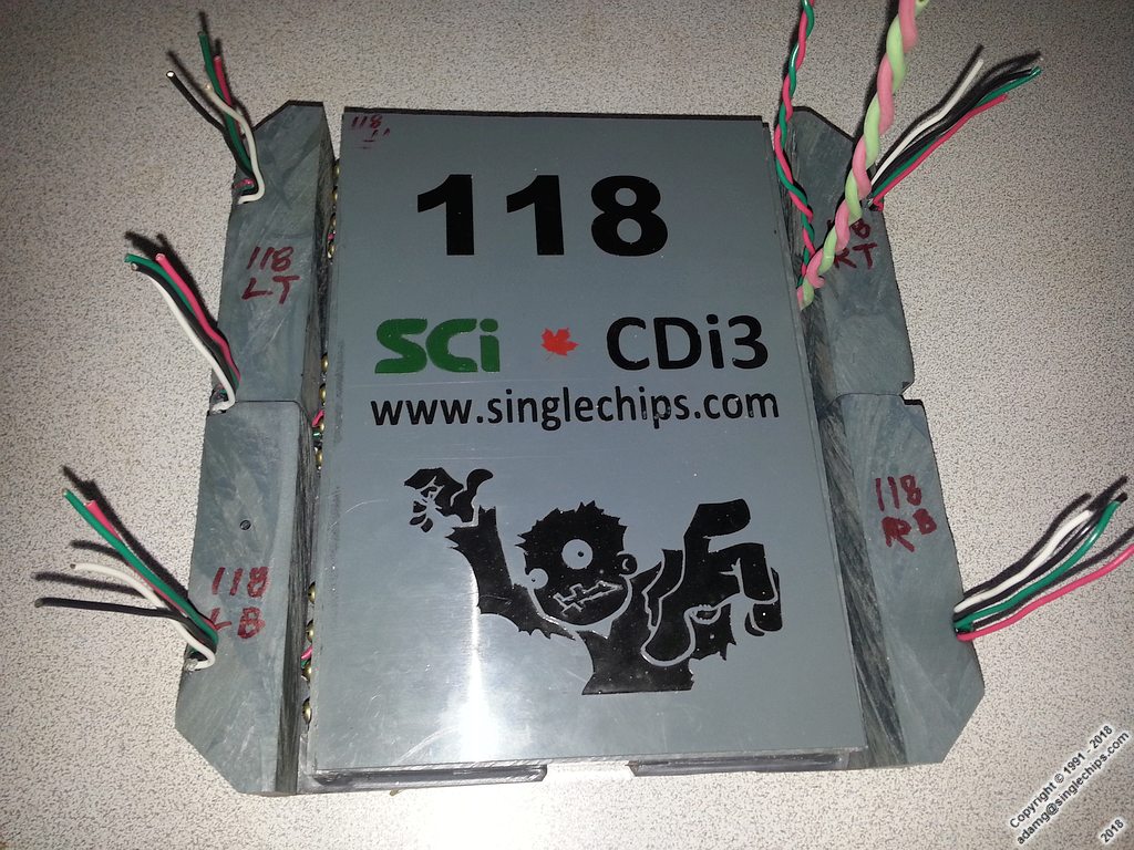
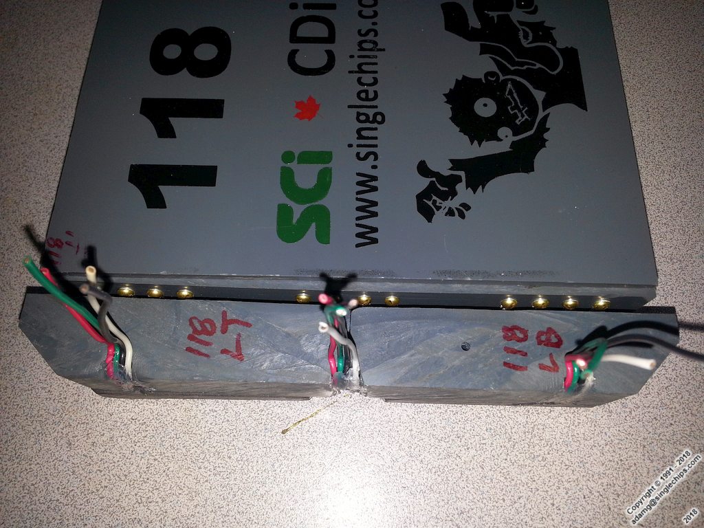
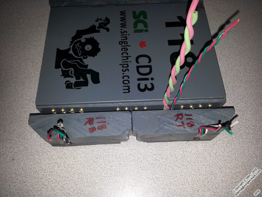
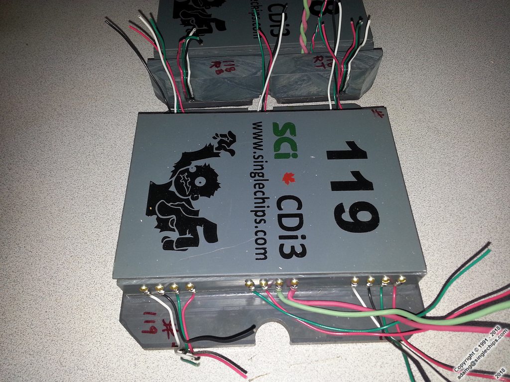
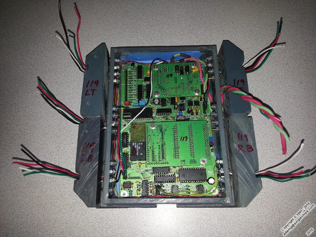
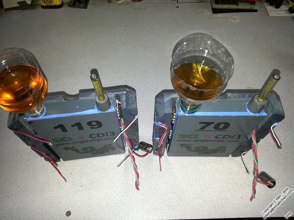
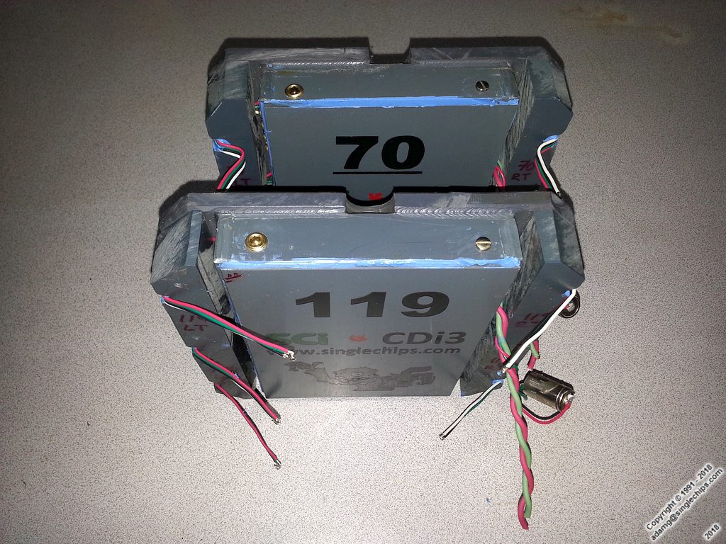
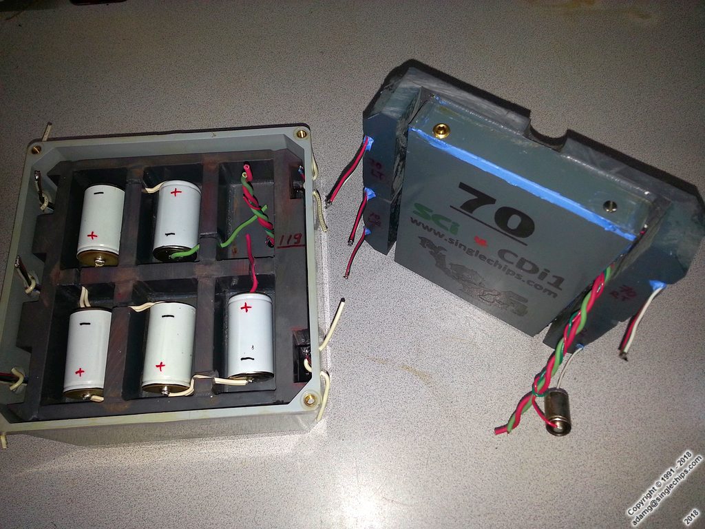
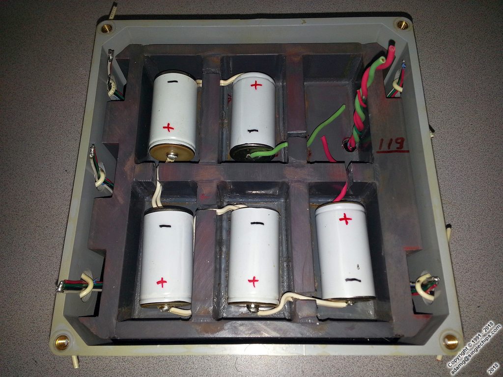
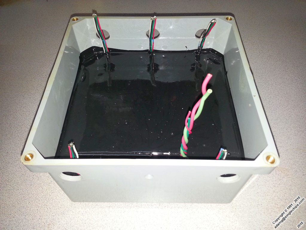
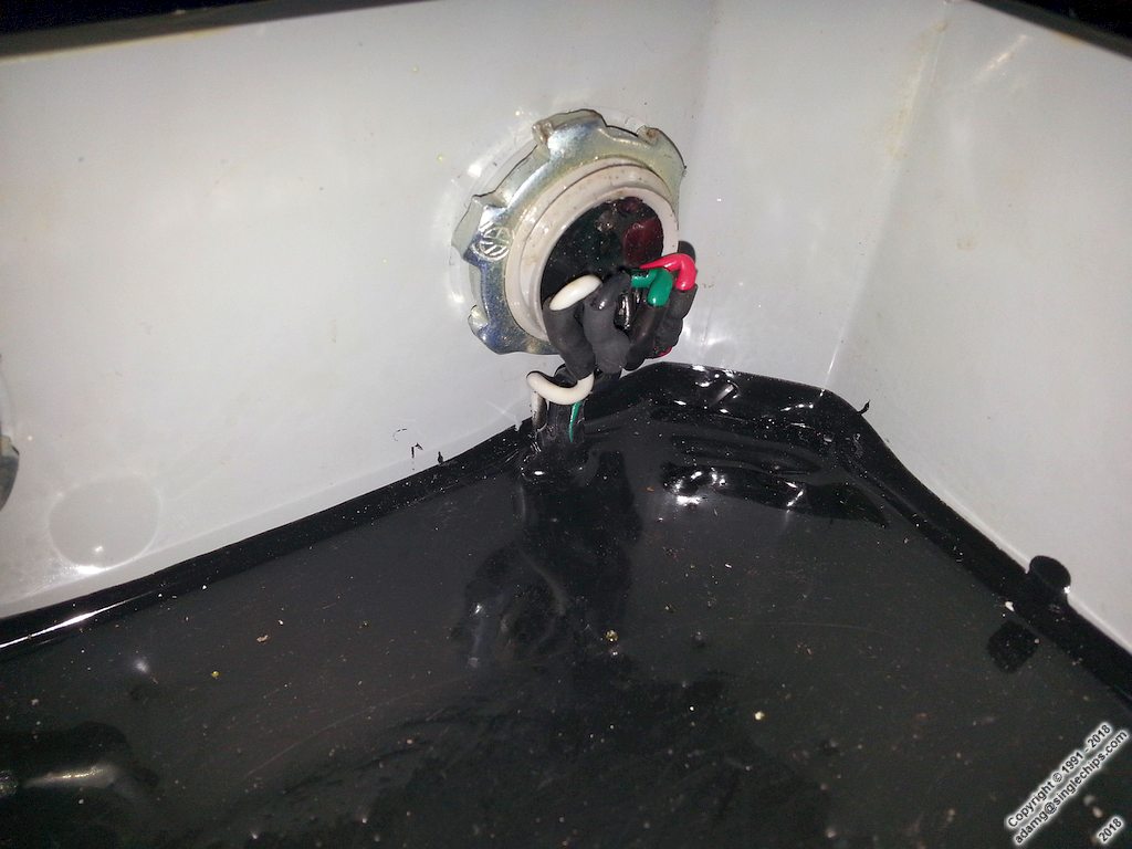
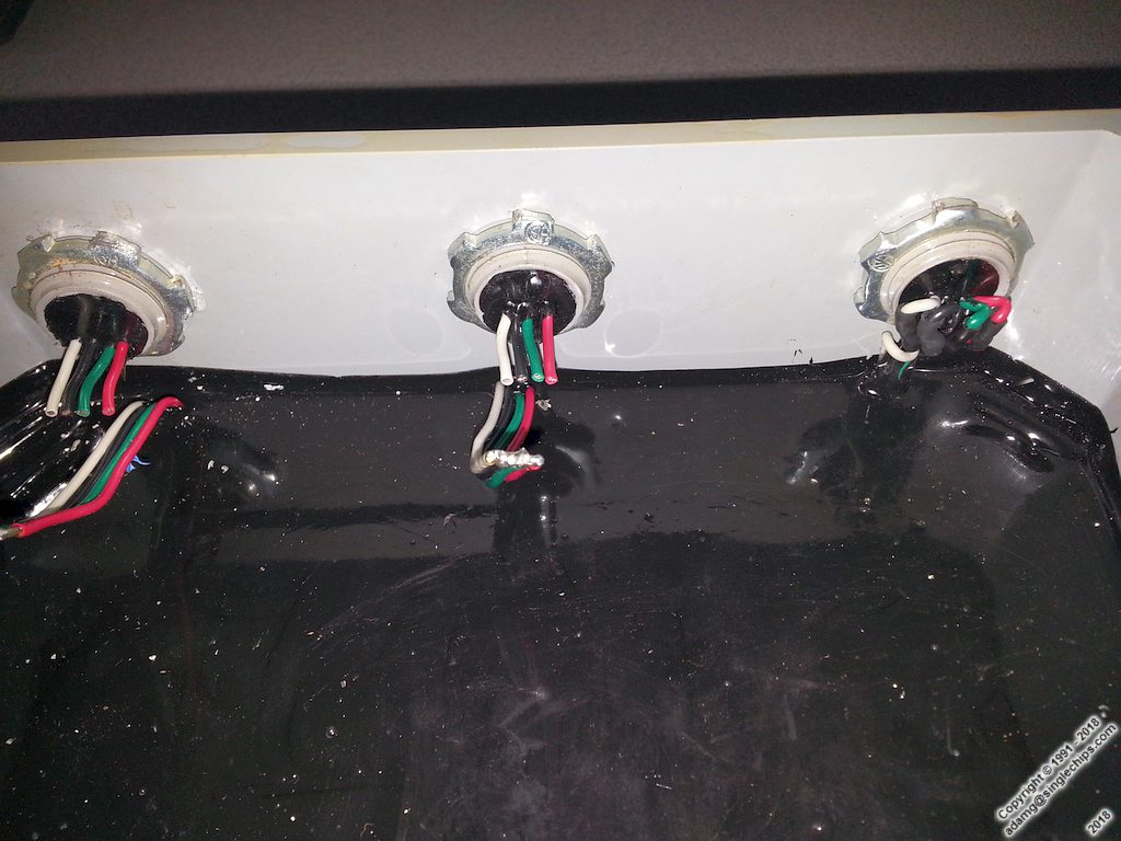
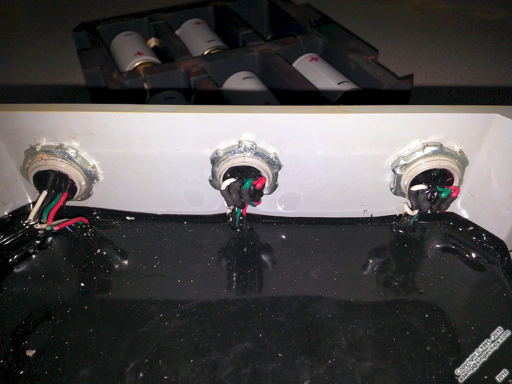
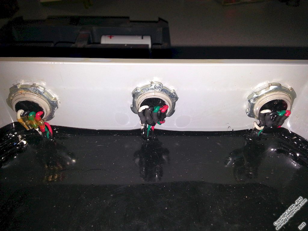
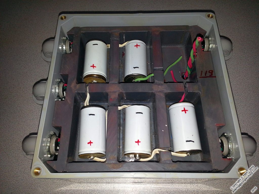
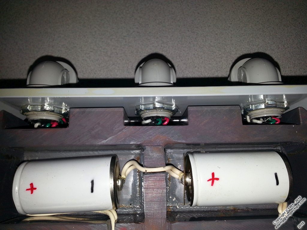
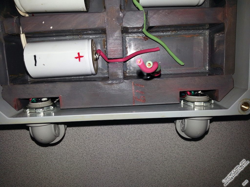
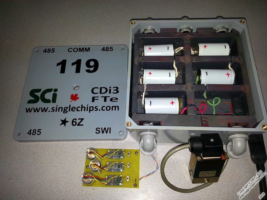
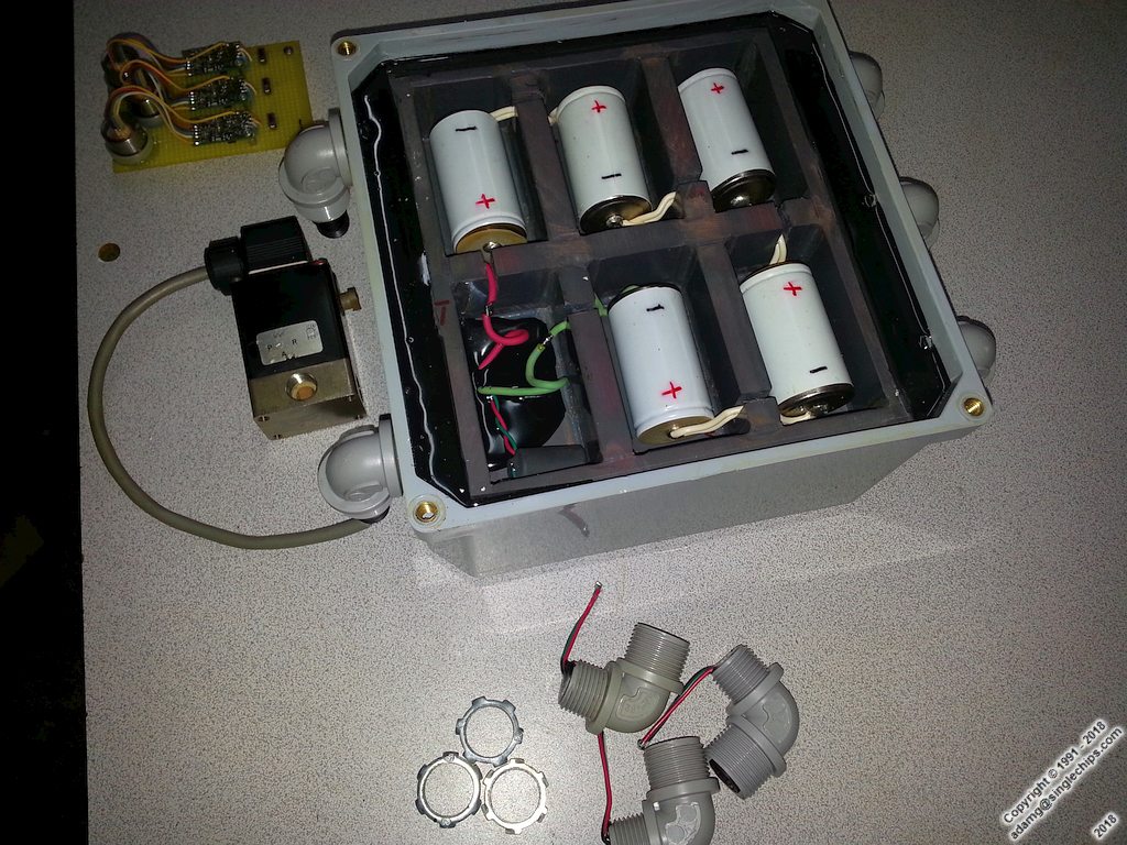
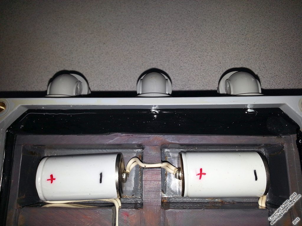
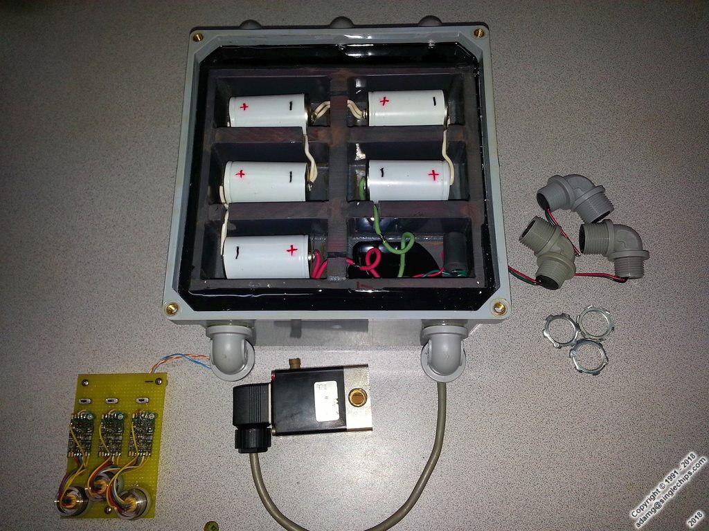
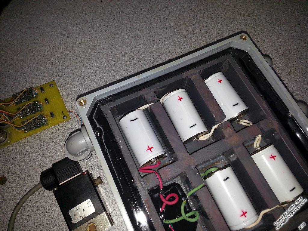
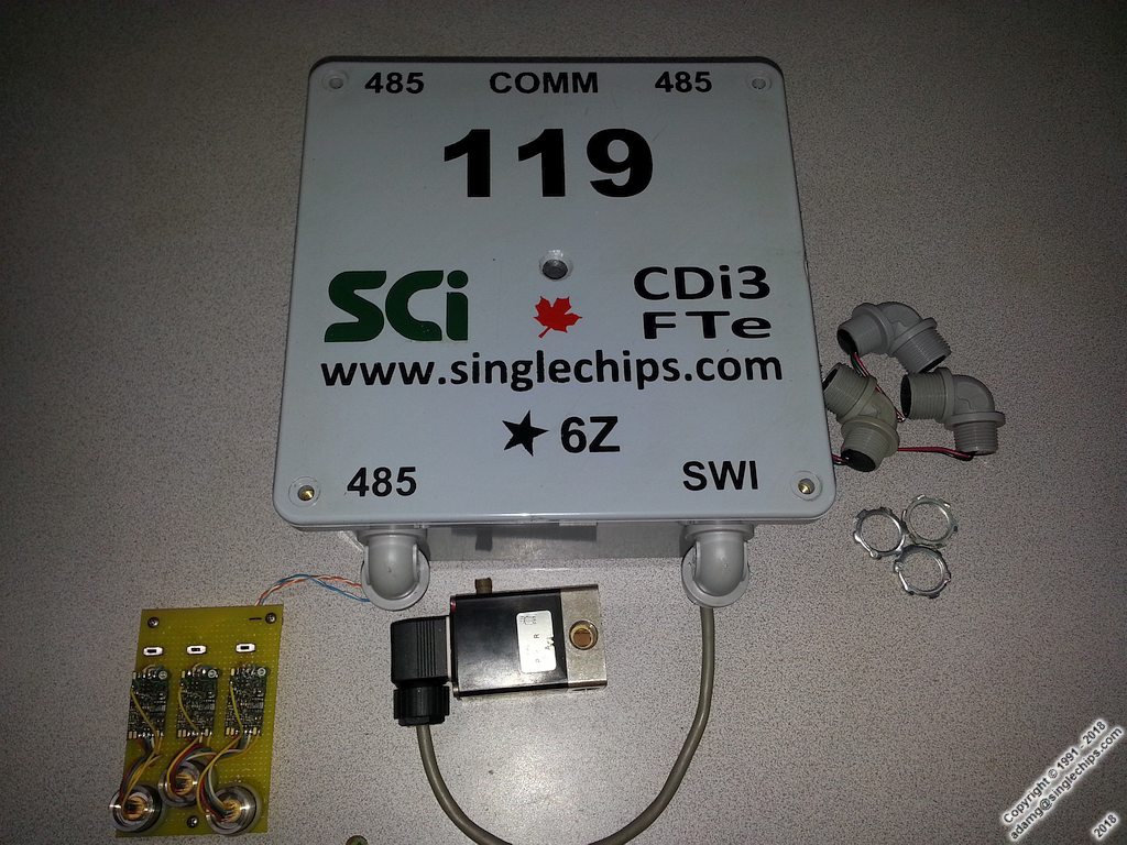
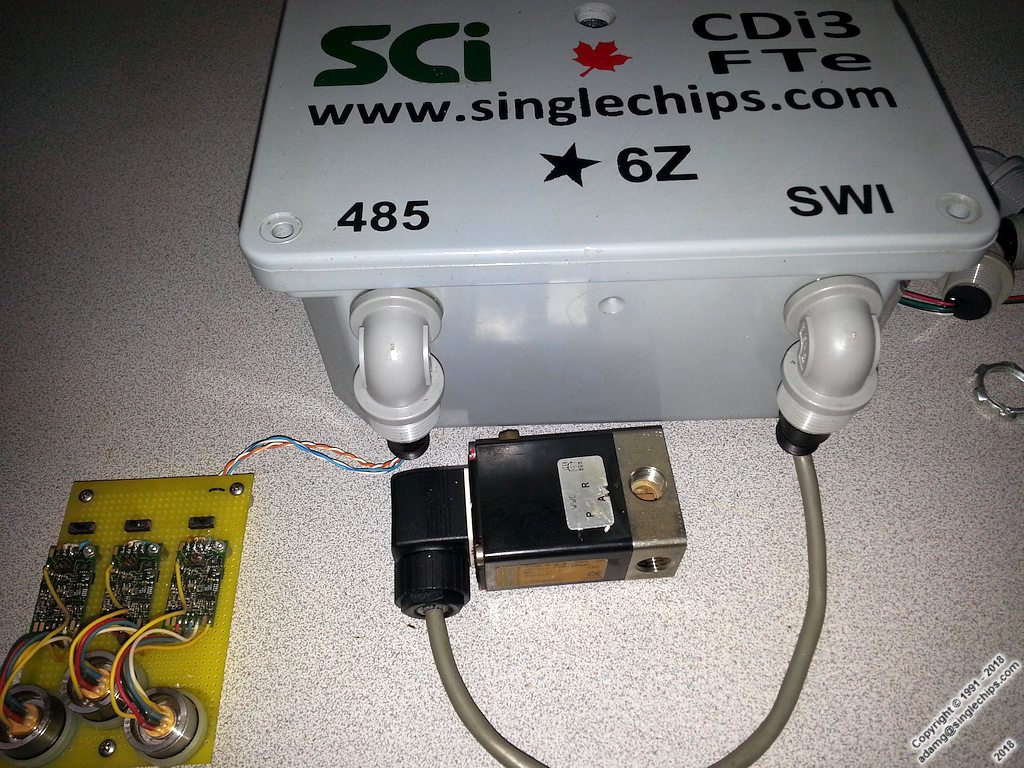
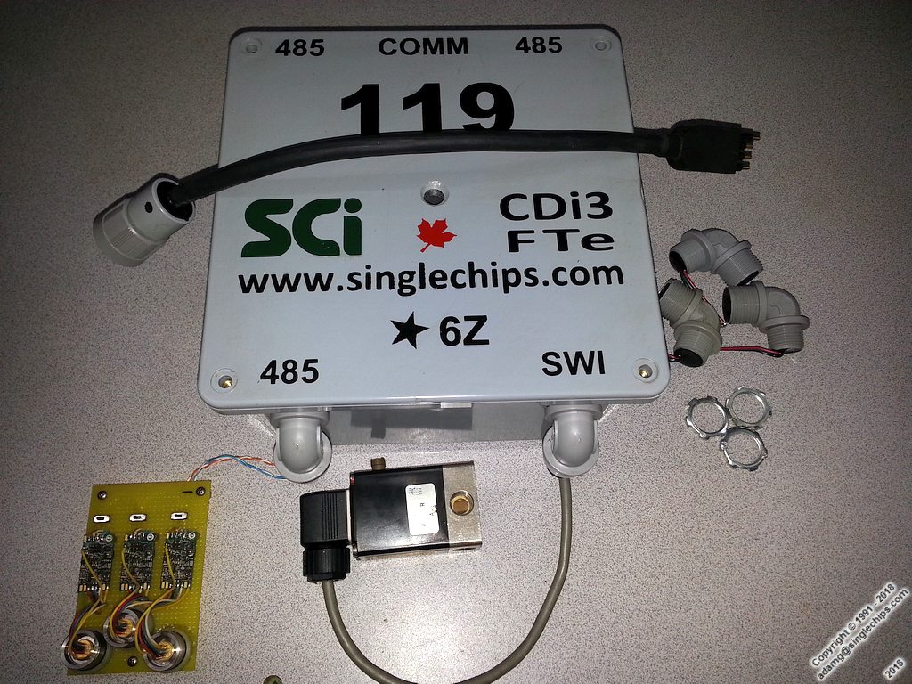
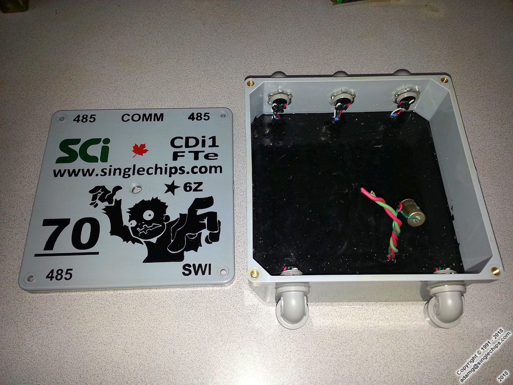
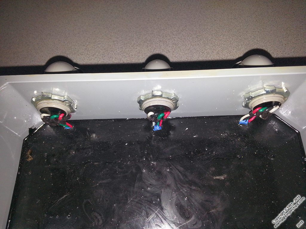
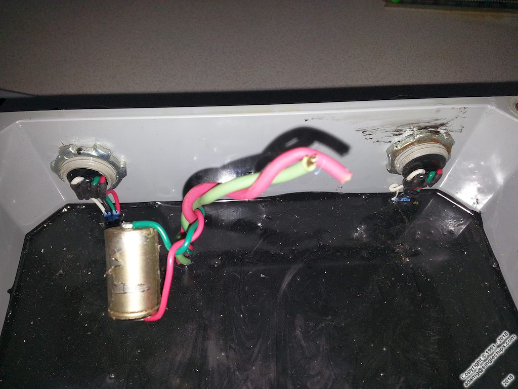
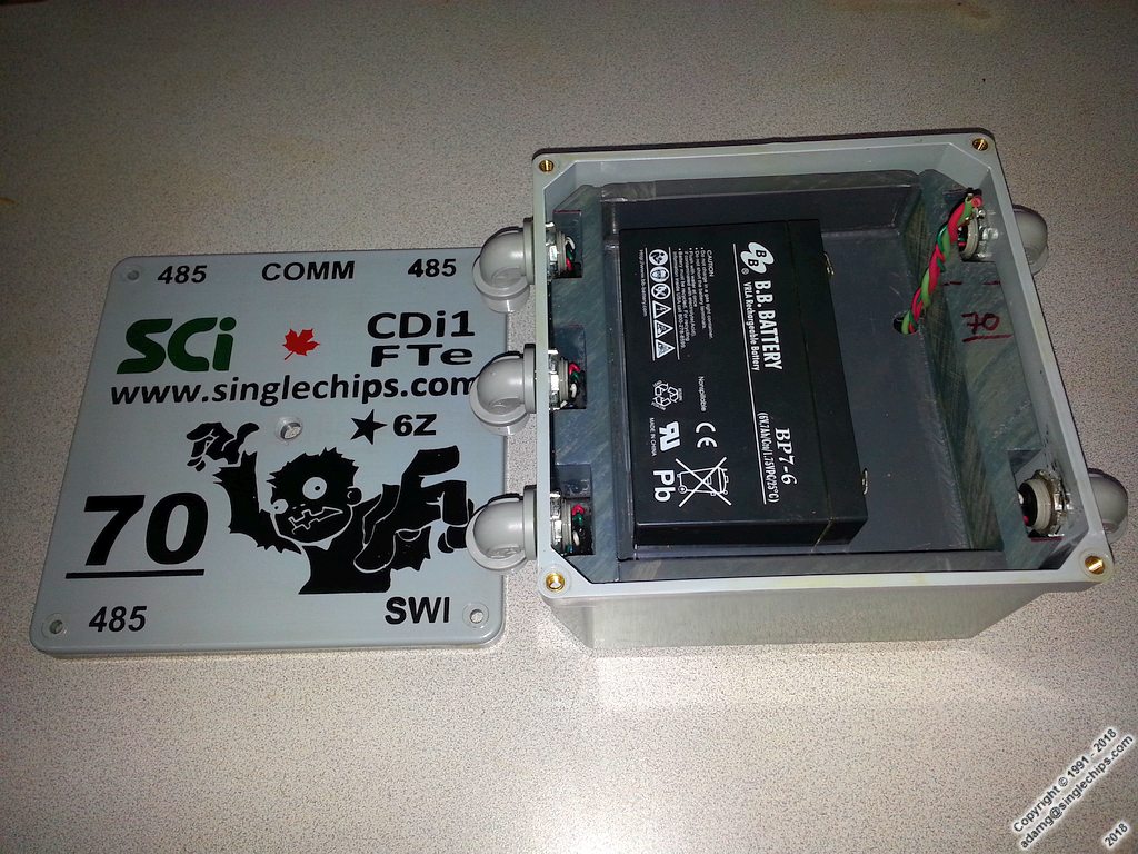
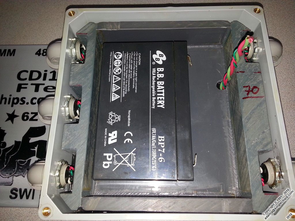
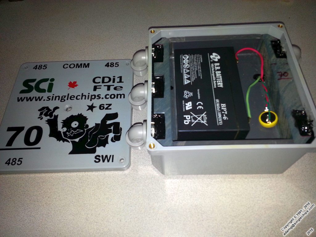
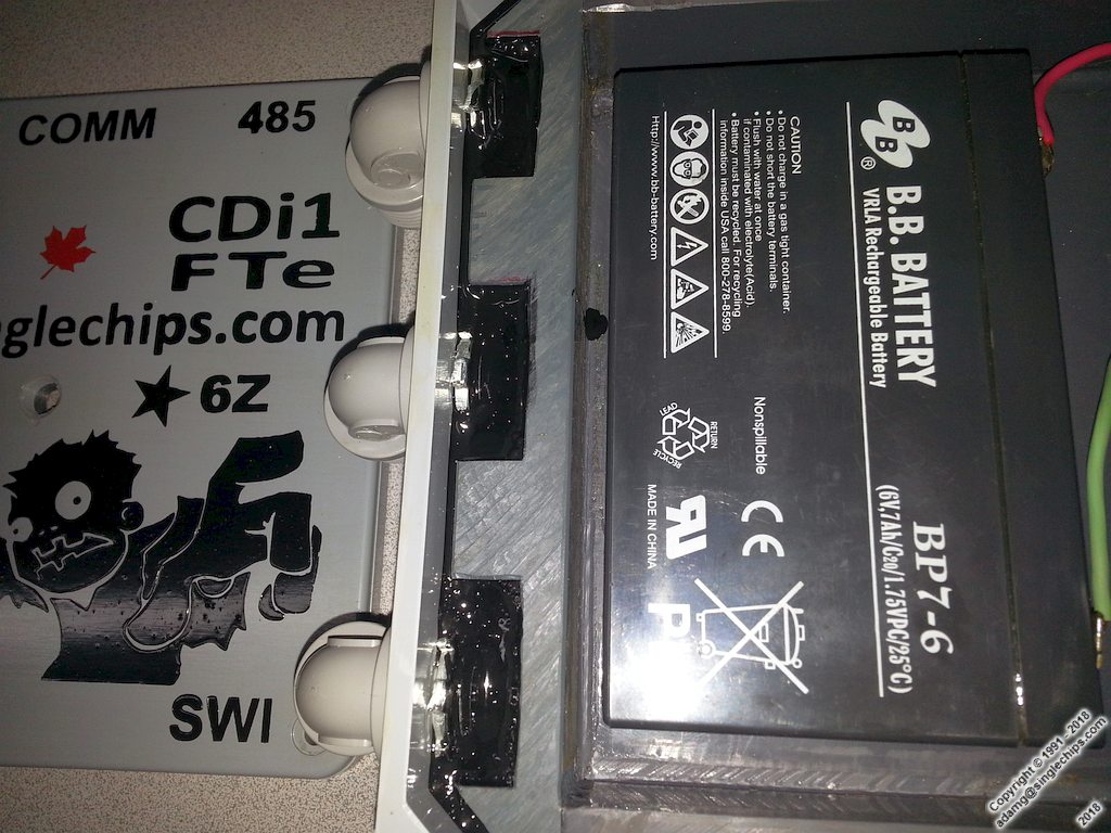
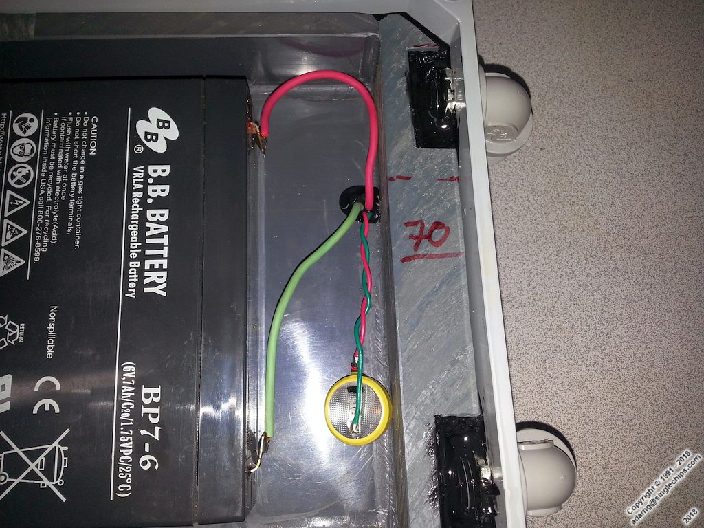
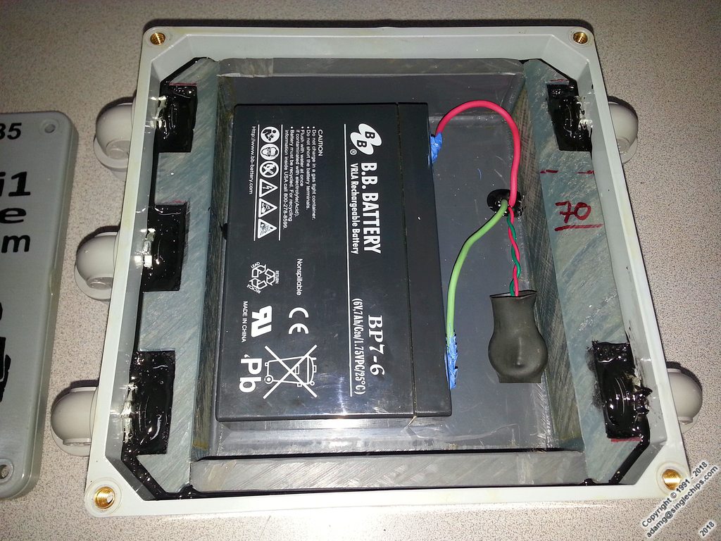
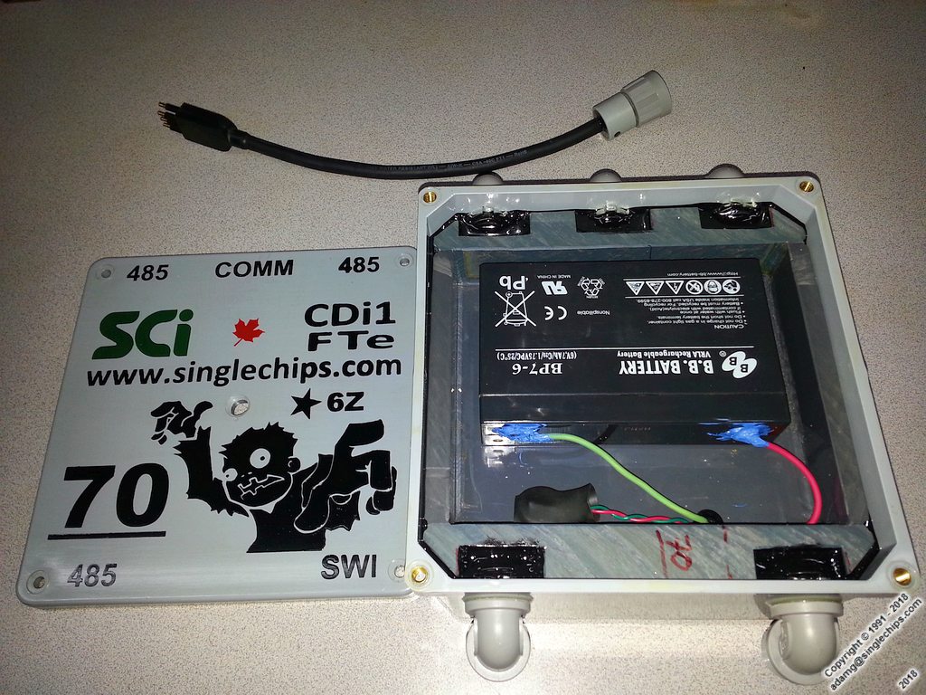
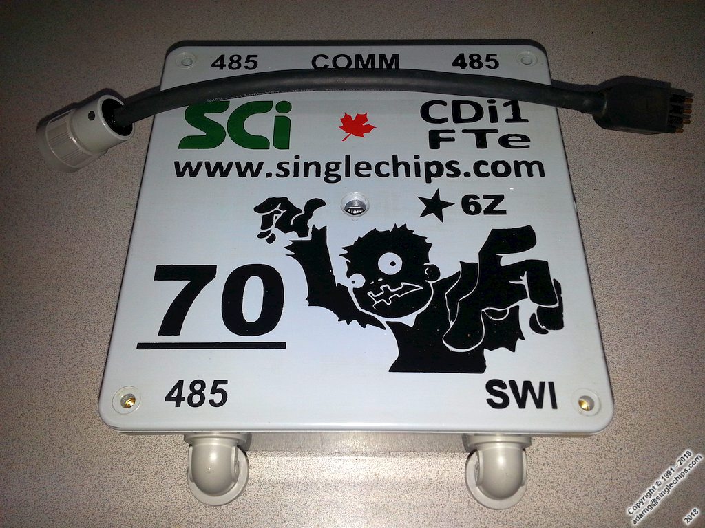
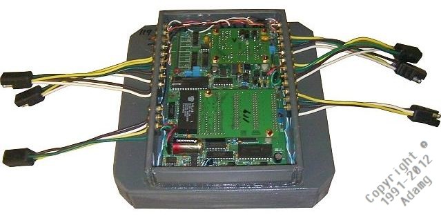
Old P7 Proto (CDi3) Board Assembly Method Pictures, June 2011 (Obsolete)
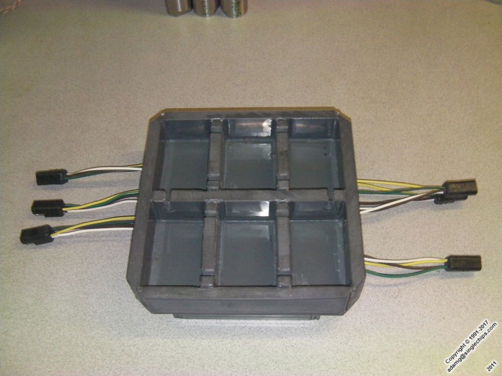
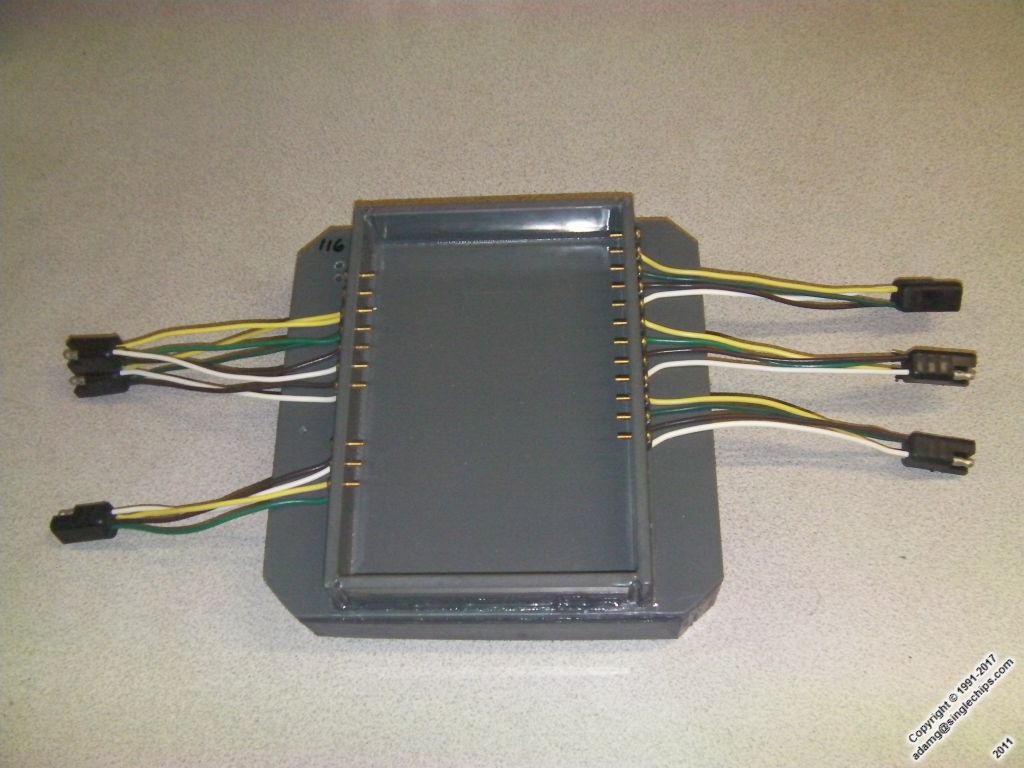
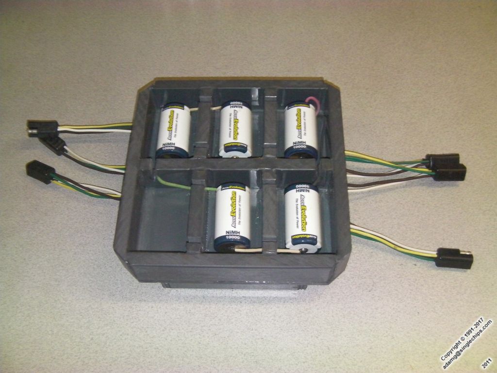
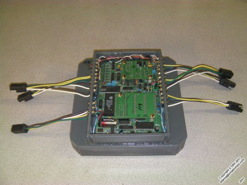
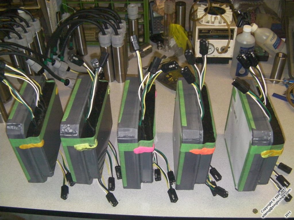
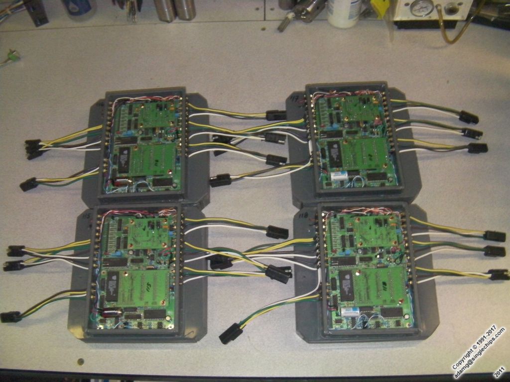
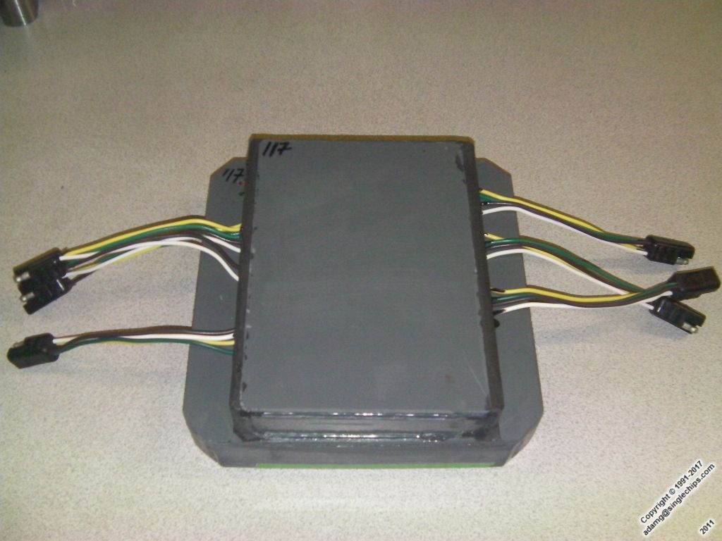
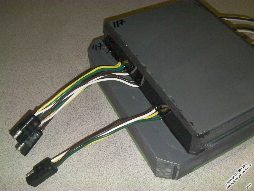
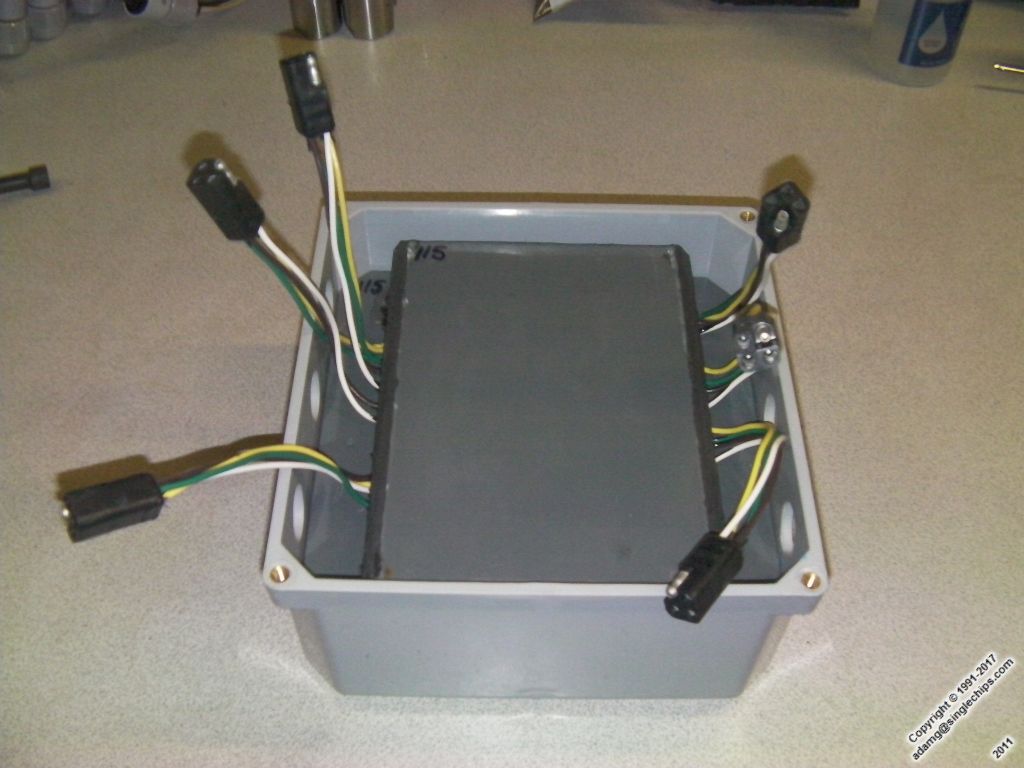
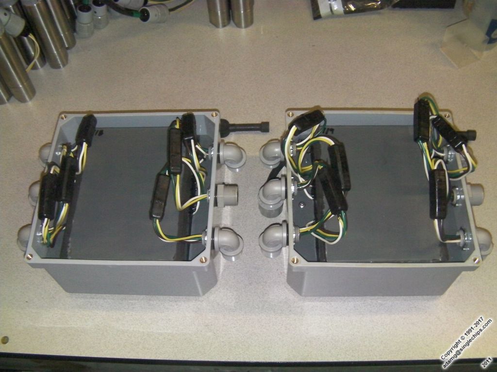
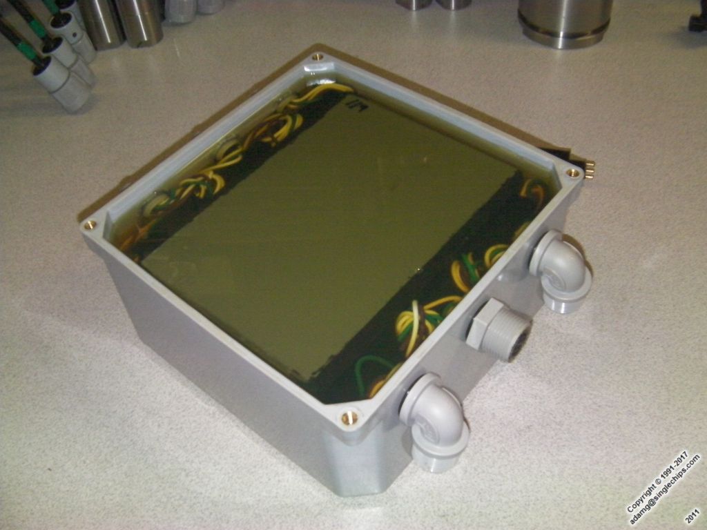
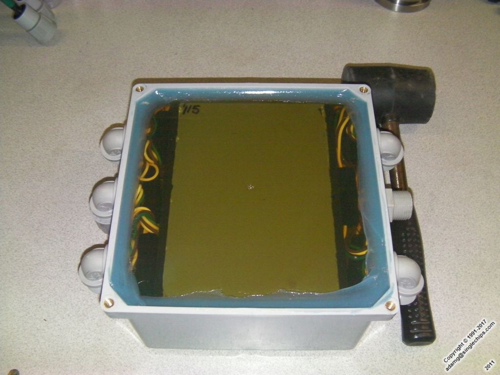
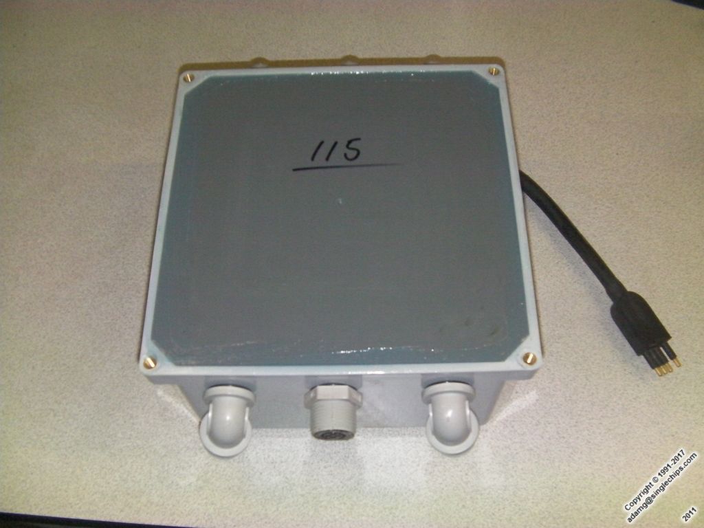
  • All air is vacuum-evacuated from both the battery and board compartments while the potting compound sets. Once the wiring is finished and tucked-in neatly, the entire assembly is potted the same way.
  • Since no air or very little air remains, the assembly is rendered incompressible.


Bottom of welded PVC case
Top of case with wires attached
Bottom with batteries wired
Lid
Box with bottom piece inserted
Batteries potted
Some wiring done
Board inserted and wired
Sides potted. Yes, that is play-doh...
More boards
Finished potted board
Potted side detail
Finished board inserted into box
External connections finished/tested
Potted
Silicone around the rim
Finished
P7:
Obsolete!!!
Contact:
SCi.RS Cloud (Mirror of singlechips.com)SingleChips Greece Cloud (Mirror of SingleChips Greece)NuovoPicus CanadaXYZ CanadaSingleChips GreeceSCi.RSCensors!!!Censors!!!Censors!!!
Copyright © 1991-2024 AdamG Last Update: Tuesday, July 06, 2021 2:53:21 PM